picture

MCU chip decryption and cracking method

How do single-chip microcomputers and digital circuits resist interference?

(Click the red letter above to get it)


01
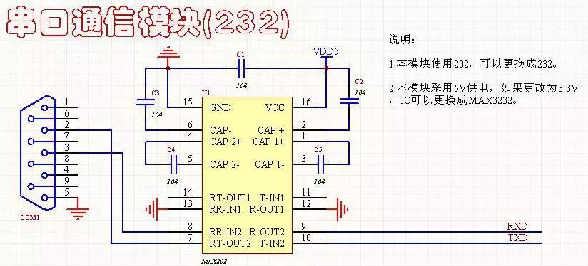
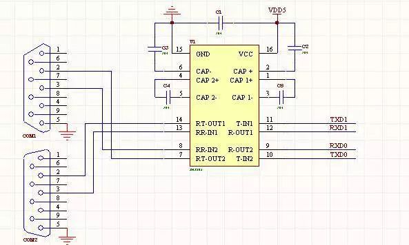
Two-way 232 communication circuit


The 3-wire connection method corresponds to the female connector, the working voltage is 5V, and MAX202 or MAX232 can be used.

picture

02
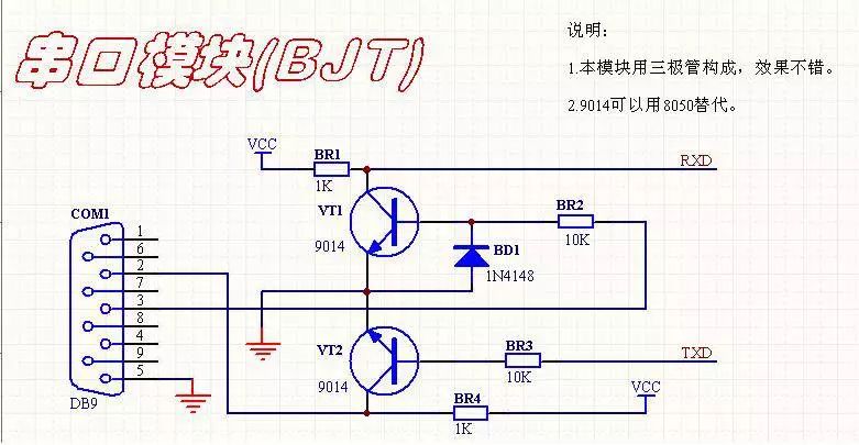
Transistor serial communication


This circuit is built with triodes, the circuit is simple and the cost is low, but the problem is that it is generally very good at low baud rates.
picture
03
Single 232 communication circuit
The three-wire method is completely equivalent to the above three-stage pipe.
picture
04
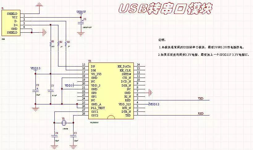
USB
The PL2303HX is used, which is cheap and has good stability.
picture
05
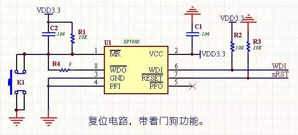
SP706S reset circuit
With watchdog and manual reset, the price is cheap (Maxin's is much more expensive), R4 is used for debugging, after debugging, solder R4.
picture
06
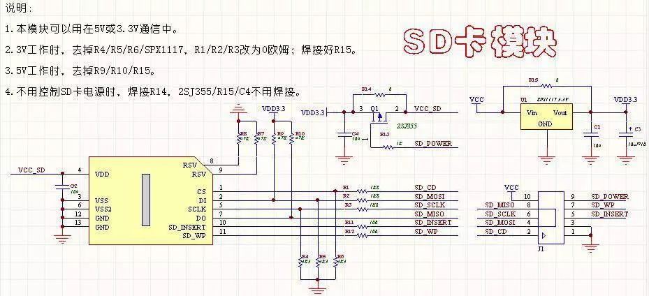
SD card module circuit (with lock)
This circuit is related to the package of the SD card, please note that it corresponds to the package. This circuit can control the power supply of the SD card through the port, which is relatively complete and can be used for 5V and 3.3V. However, it should be noted that the use of some devices, 5V and 3.3 are not the same.
picture
07
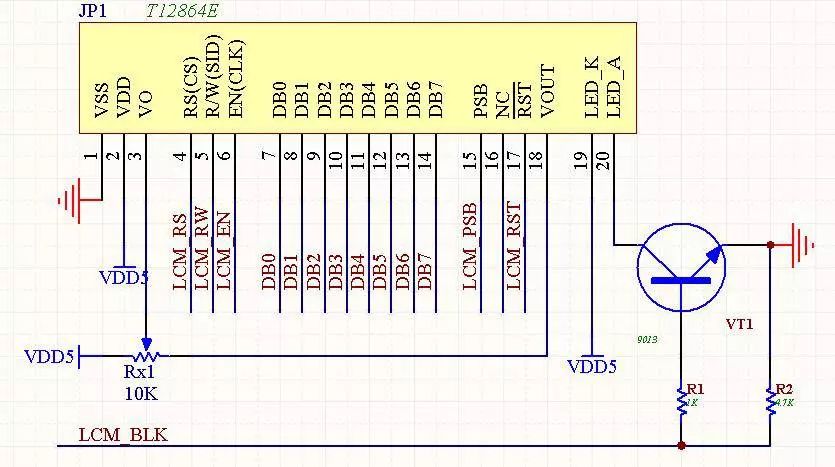
LCM12864 Liquid Crystal Module (ST7920)
This circuit is a common 12864 circuit, which is cheap and has a Chinese character library. It can be set to work in serial mode or parallel mode through the level of the PSB port, with backlight control function.
picture
08
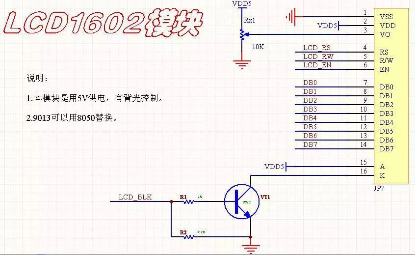
LCD1602 Character LCD Module (KS0066)
The most commonly used character LCD module, which can only display numbers and characters, can be controlled by 4 or 8 digits, and has a backlight function.
picture
09
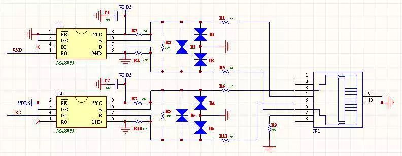
Full-duplex RS485 circuit (with protection function)
With protection function, full-duplex 4-wire communication mode, suitable for long-distance communication.
picture
010
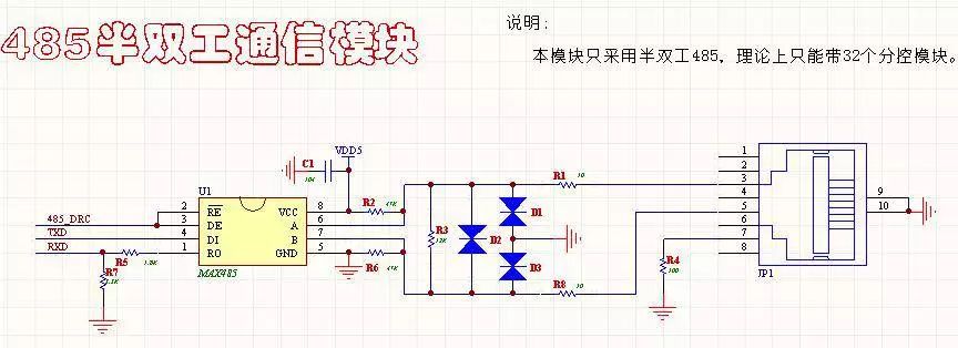
RS485 half-duplex communication module
The data transmission direction can be selected by selecting the port, with protection power. This module can only work at 5V.
picture
011
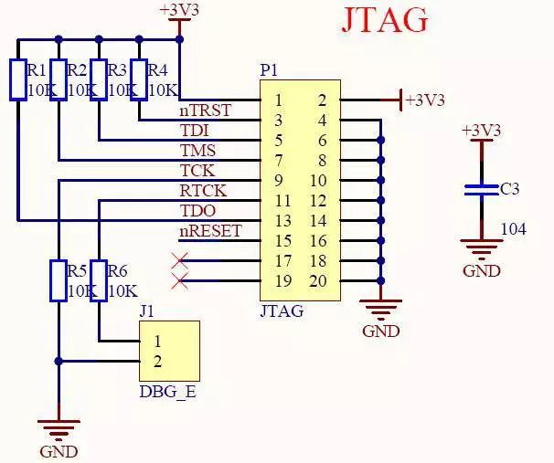
ARM JTAG emulation interface circuit
It is relatively complete and can be applied to conventional ARM chips with automatic download function, which can be used with JLINK or ULINK.
picture

Source: Internet


Past recommendations:

Sparks fly! Failure Mechanism Analysis of Various Electronic Components Hot~

Jobs' resume of 1.2 million was auctioned, and HR wanted to hit someone... New~

Haha, if the computer was invented by the Chinese, how should the code be written?

Here are the interview questions for hardware engineers, do you dare to try it?

Analysis of the advantages and disadvantages of 7 mainstream single-chip microcomputers

Absolutely! Foreigners teach you DC-DC and make a switching power supply

pictureIf you have any knowledge that urgently needs to be supplemented, please leave a message to the editor in the comment area below.

picture

like? poke poke