Drawing Class | A detailed explanation of the SU plug-in, I wish you a hand in modeling
July 25, 2022
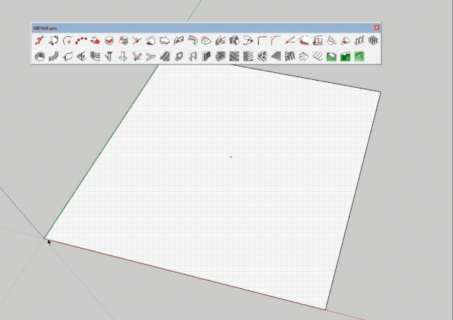
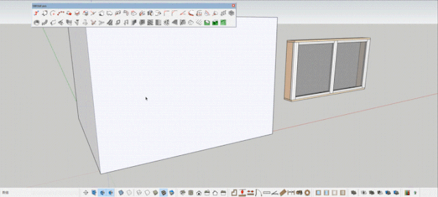
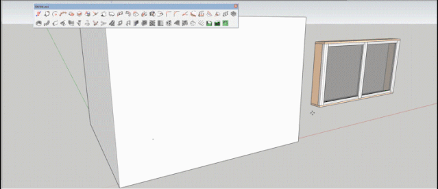
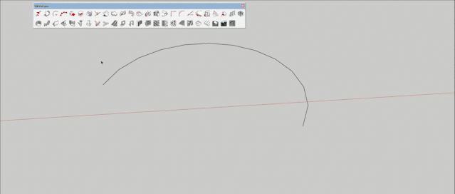
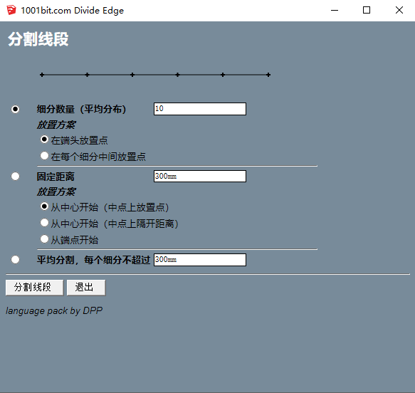
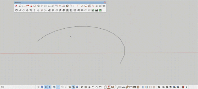
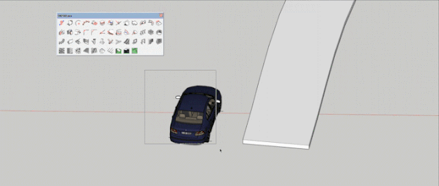
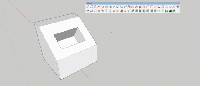
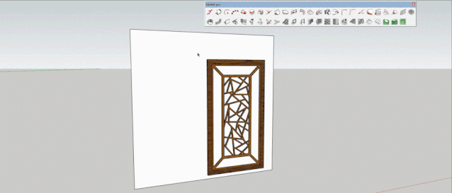
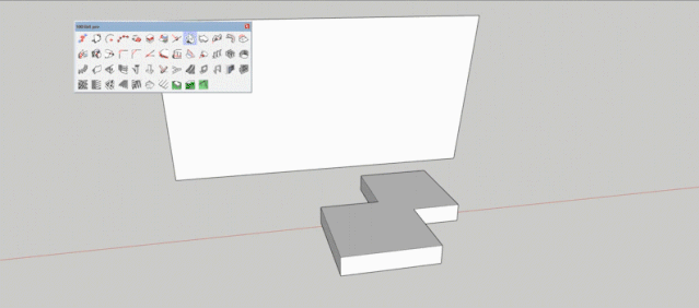
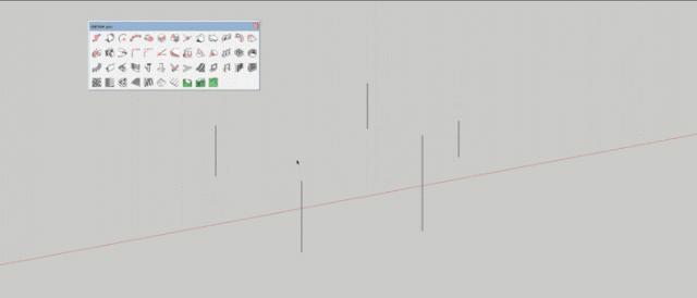
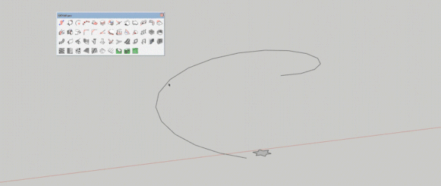
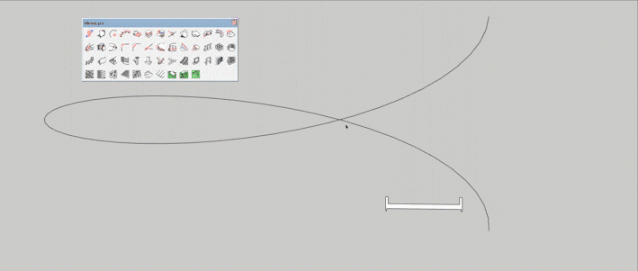
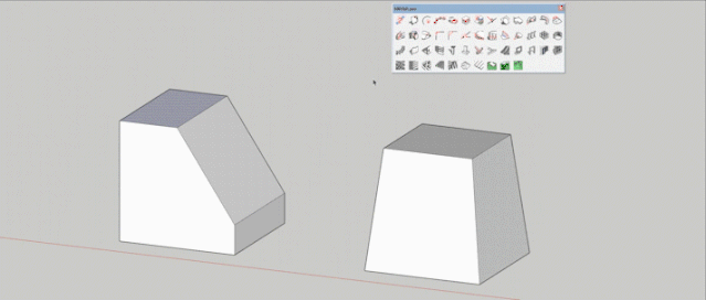
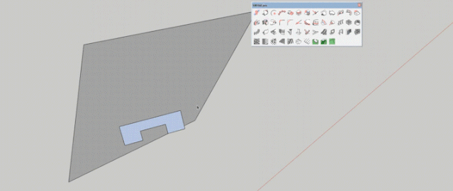
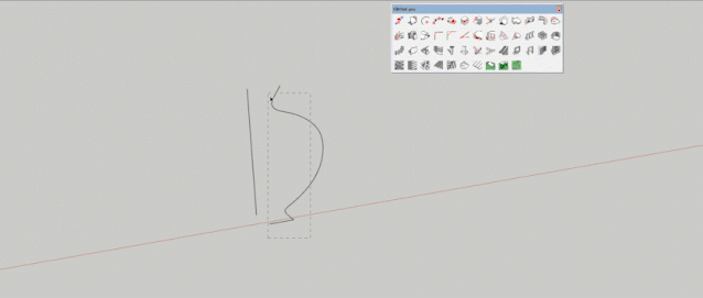
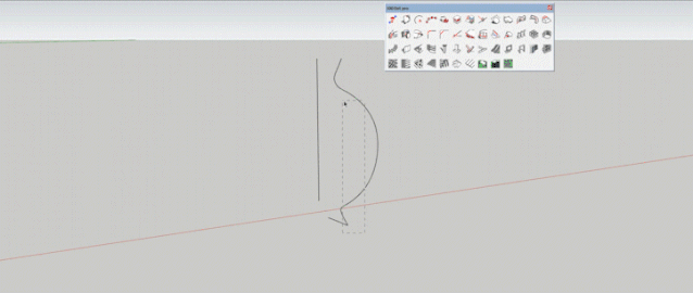
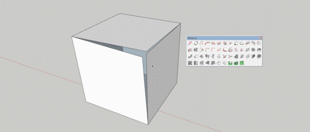
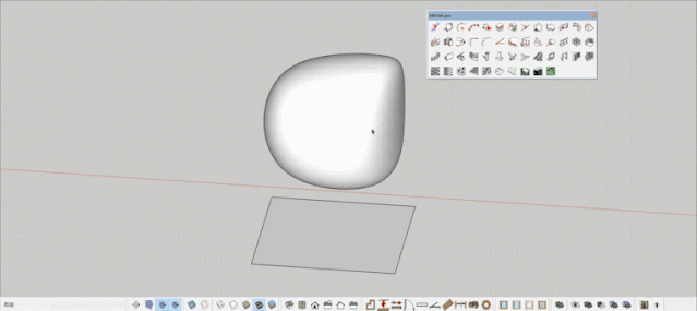
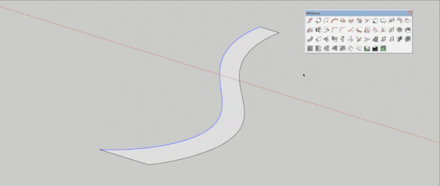
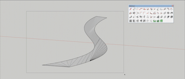
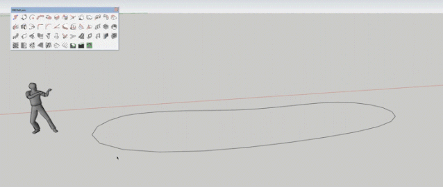
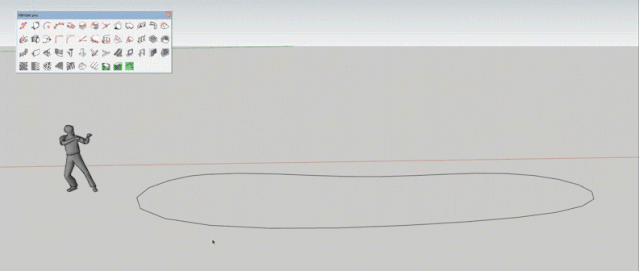
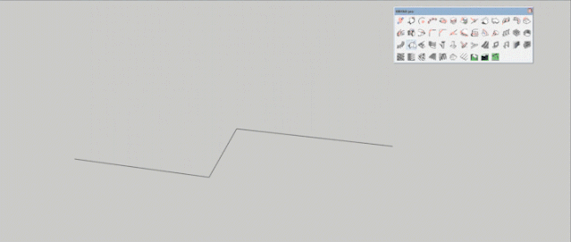
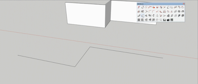
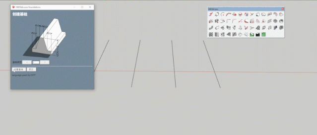
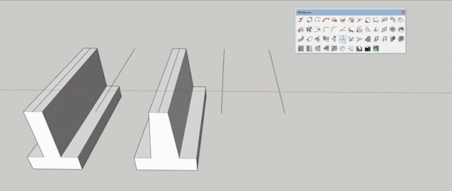
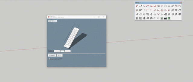
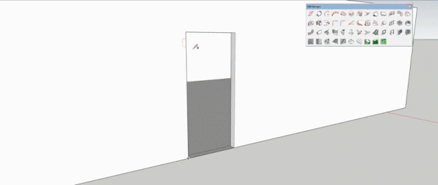
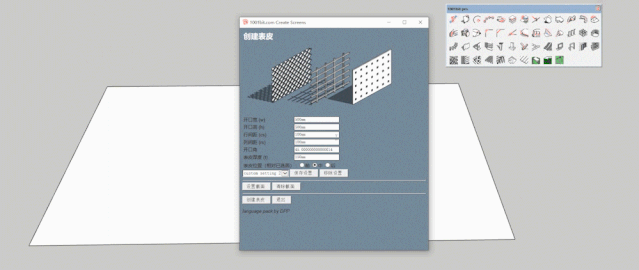
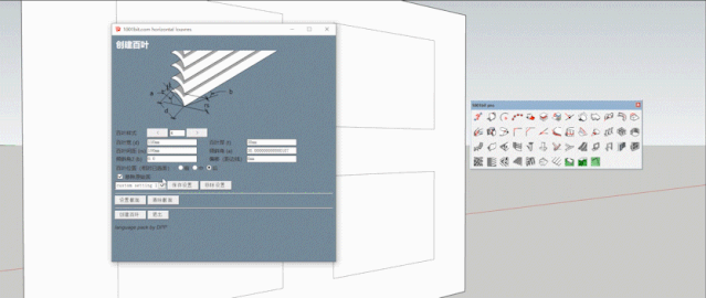
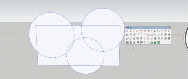
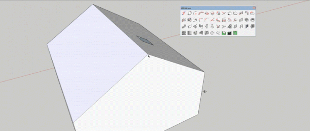
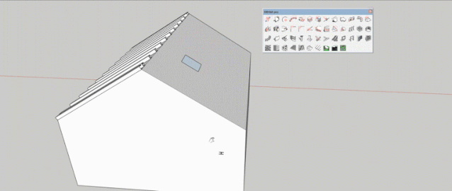
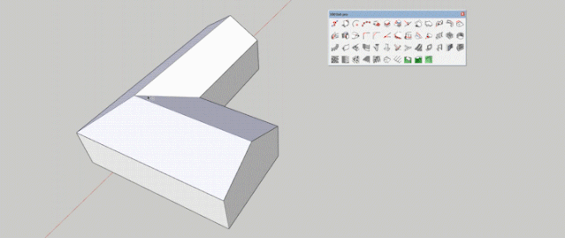
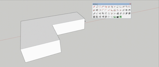
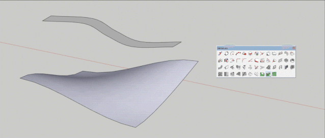
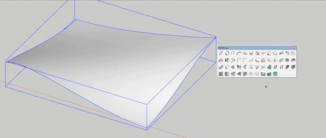
Recently, I have received a lot of private messages from people It's about to enter the craze for submissions to landscape competitionsHowever, I am still a mess about modeling.Has a lot of plugins but most of them don't work My sister receives your voice Specially launched a new seedling drawing class For software operation, Amway software, competition skills, etc.Give you the best knowledge Raise your greatest abilities We will see you in Xinmiao The plugin we introduce today is called 1001bit pro It is a powerful collection of professional plugins for architecture Has many useful functionsVarious architectural elements can be made quickly Also includes some drawing and editing tools Let's learn together↓ ↓ ↓1- Comprehensive information between two points How to use: Click the tool and then click the two points to be measured to obtain it.Significance: It is mainly used for information between points. Our frequency of use is not high. It is good for everyone to understand. 2-Defining point on face How to use: Click the surface to be marked → click tool → select the base point on the surface → enter the data in the horizontal direction, press Enter → enter the data in the vertical direction and press Enter, you can get the point you want to mark. Then place the object to be placed on the point.Meaning: This tool can set the horizontal and vertical distances separately to add construction points on the selected face. This tool can be used to make reference points, especially for some non-vertical and non-horizontal faces. 3- Find the centers of circles and arcs How to use: Click the tool to find the center of circle and arc in the toolbar → select three points on the arc at will → you can get the center of the circle or arc. Significance: It is convenient to find the center of a circle or arc, and it is convenient to place objects. 4- Divide How to use: This tool has a lot of possible segmentation methods. The first one is classified according to the number of divisions and has two branches, the second is classified according to a fixed distance and has three branches, and the third is average segmentation. It is easier to understand that this article takes the first branch of the second type as an example.↓ ↓ ↓ First select the line segment to be divided → click the tool → select the second segmentation method and select the first segmentation method and input the segmentation data. This picture is based on 300 as an example → the segmentation can be completed.Significance: This feature is especially useful for sorting, especially with balustrades.5- Align solids How to use: first select the entity component or group → click the tool → select the three origin points of the component or group → select the corresponding three target points, so that the sub-component or group can be accurately positioned. Significance: This tool can align selected components or groups by three points, and is especially useful for precise alignment on non-planar surfaces, such as placing a car on a ramp, or placing a window on a slope. 6- Draw a line perpendicular to a known edge or face How to use: Click Tools→Pick Start Point, point to a line segment or a surface, if the object is a line segment, a line perpendicular to the line segment will be drawn, and if the object is a surface, a vertical line perpendicular to the surface will be drawn. 7- Draw the face on the plane defined by the 3 points method one Method Two How to use: There are two ways to use this tool. One is to select all the drawing objects → click the tool → pick three arbitrary points on the drawing surface → you can get a complete projection drawing.The second is to draw the object manually. First, click the tool → select three points on the drawing surface → click the point on the drawing object → the corresponding point will appear on the drawing surface → double-click to end.Significance: This tool is especially useful when a certain face is alerted to section projections, or by drawing faces by following non-coplanar points. 8- Draw a best fit surface defined by several points (points do not have to be coplanar)How to use: Click Tools → Click on the non-coplanar point and double-click to complete the editing.Significance: This tool generates faces from a series of non-coplanar points, this tool is especially useful for patching non-coplanar points in some models. For example to draw the roof from under some rafters. 9- Loft along the path How to use: first double-click the path to select all → click the tool → the mouse turns into a red square, then select the face of the stocking object → the mouse turns into a red cross again → after setting out a point of the object → click a point on one side of the path → complete . 10- Loft along the path (keep orientation)How to use: first select the curve → click the tool → pick the point on the section with the red square (note that the section must be on the XY plane, and the top is in the Y direction) → pick the reference point on the section → pick the reference point on the curve corresponding to the section reference point. At this time, the curve is still in the selected state, and you can continue to set out the armrest.Significance: This tool is often used for section ramps, such as bridges, parking ramps, spiral staircases, etc. This tool can maintain the vertical direction of the section after lofting. 11 - Tapered stretch How to use: Select the surface to be extruded → click the tool → use the mouse to move the direction to pick or enter a precise distance → the trend of the extruded surface is maintainedSignificance: This tool stretches the surface while maintaining the direction trend of the surface in space 12- Push and pull the plane to the target plane How to use: Select the face to be pushed and pulled → click the tool → use the mouse to select the face in the direction of the push → push and pull to the face is still an independent face, and the direction and angle of the push and pull are still preserved Significance: This tool stretches the surface while maintaining the direction trend of the surface in space 13 - Rotation face When the rotation angle is 360° When the rotation angle is 270° How to use: Select the curve to be rotated → click the tool → enter the rotation angle, precision division and scale parameters, click the create button → pick the reference point 1 of the rotation axis → pick the reference point 2 of the rotation axis → complete the rotation surface.Significance: This tool can rotate the surface according to the reference curve and shaft penetration, and can also scale to form the selected surface. The scaling function refers to the ratio of the original distance from the relative point to the axis to the final distance. 14 - Mobile endpoints How to use: Click the tool → pick the endpoint to be moved → pick the target point or define the direction with the mouse, pick any direction of the crosshair, and then enter the exact distance (the arrow keys can force a specific moving direction, left-green Y, right- Red X, Up - Blue Z, Down - Cancel specific direction)This tool enables flexible editing of a single endpoint of the model 15-Chamfer circle How to use: Click the tool → select two sides respectively → enter the radius of the rounded corner and the number of subdivisions → you can complete the editing → you can continue to select two sides 16-Chamfered corners How to use: Click the tool → select two sides respectively → input the chamfering data and subdivision number of the two sides → press Enter to complete the editing → you can also continue to select two sides17-Extend line segment How to use: Click the tool → select an edge → move the mouse to another edge or click the left mouse button on the face → finish editing. 18 - Offset How to use: Click the tool → enter the offset distance data → select the edge → move the mouse to select the offset direction → complete the editing. 19-Horizontal split surface How to use: Select the object to be divided horizontally → click the tool → pick a point to define the base plane → pick the target surface or enter the distance → the surface is divided horizontally Meaning: This tool can split surfaces horizontally 20- Create the ramp How to use: select a continuous curve → click the tool → input parameters such as angle, height, scale, etc. → count to the low point of the ramp → pick another point of the ramp → complete the editing of the surface (the curve on the other side is still on the horizontal plane at this time, At this time, the curve on the other side can also be raised by the same steps) At this time, there may be a lot of random lines → you can right-click → soften the edge → adjust the strength → complete the creation of the ramp.Significance: This tool can change two edges and create a continuous ramp. The tool provides a ramp calculation method, which is created by setting the angle and scale of the ramp and the height and length of the perseverance.21 - Zoom Tool Mode 1 as an example How to use: Select a group or component → click tool → select zoom mode → mode 1: input the data of zoom XYZ → click the blue cross cursor on the group or component → complete 22 - Linear Array array one array two array three How to use: Select the component or group → click the tool → select the array method and enter the array parameters → click the create button → click the reference point of the group or component → click to pick the start point → click to pick the end point 23 - Rectangular Array How to use: Click the component or group → click the tool → enter the parameters → click to create → click the entity reference point → click the start point → pick the X direction → pick the Y axis direction → complete the creation
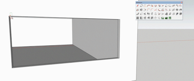
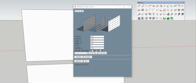
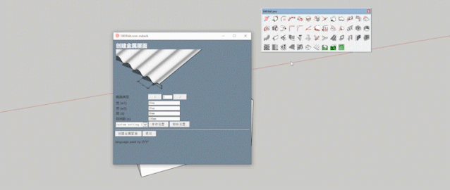
24-Polar Array How to use: Select the group or component → click the tool → enter the operation parameters → click to create an array → select the starting point of the determined rotation center axis → select the second point of the rotation center axis → complete the creationSignificance: This tool is often used to create spiral staircases and balustrades for spiral staircases 25-path array Example of the third path Example of the first path How to use: Select the path and group/component to be patterned → click tools → select options and enter data → click to create an array → click the reference point on the group/component → select the starting point of the path → complete the creation 26-Vertical Wall first wall second wall third wall Create walls How to use: Click the tool → select the wall type → enter the wall data in the dialog box → then click to create the wall → select the starting point of the wall → continue to select different points of the wall → double-click to complete the editing (or to create a wall shape, select the first One type of wall → set section → red square to select section → red cross to select wall center point/alignment is usually center → blue cross to create wall → double-click to finish editing)27- Windows on the wall How to use: Click Tools→Enter window opening parameters→Click Save and select preset settings→Click to create openings→Click a reference origin on the wall→Enter precise data in the horizontal direction or select with the mouse→Enter the vertical direction data or mouse Select → Finish Create You can also create a custom shape opening, click the tool → click to create a shape → select a horizontal plane to define the shape and the remaining steps are the same as above28-Horizontal groove How to use: Select the face → click the tool → enter the corresponding parameters → click to create a groove → select the starting horizontal line (lower groove line) → complete the creationWhat it means: This tool can create horizontal concave grooves or raised lines on selected faces, and create wrinkles on irregular shapes through the softening function. 29 - Pillar How to use: There are five column methods. This article takes the fourth column as an example. Click Tools→Select the column form→Enter the parameters and click Create column→Click the insertion point (the center of the bottom surface of the column)→Click the rotation angle 30-Basic first foundation Different parameters for the second basis Different parameters for the second basis How to use: Click Tools→Select Column→Modify Parameters→Click Create Foundation→Select Point to determine the active foundation path→Double-click the last point to create a foundation or click the first point to create a closed foundation (left arrow-green Y axis, Right arrow - red X axis to reason the arrow keys along the XY axis and type the exact distance) 31- Create the stairs Different types of stairs Two-step staircase and spiral staircase How to use: Click Tools→Select Stair Style→Input Parameters→Click to Create Stair→Select Insertion Point→Select Rotation Angle 32- Create the escalator How to use: Click Tools→Enter parameters and click Create Escalator→Select the starting point→Select to confirm the direction or select the end pointSignificance: The tool automatically creates standard escalators. Standard components are sized to match commonly available stairs33-Window frame How to use: Create a door opening on the wall as a section of the window → select the surface → run the tool → input parameters → complete the creation → modify the material of the window35-door frame How to use: Create a door opening on the wall as a section of the door → select the surface → run the tool → input parameters → complete the creation 36 - Split Panel 使用方法:点击工具→选择类型→输入参数→点击面上需要创建的位置→完成创建 37-分割面 使用方法:点击面→点击工具→选择类型→输入参数→点击确定完成创建意义:该工具把选中的面分为不同的带框的面。步骤和窗框以及门框相似。关于框的截面的选项是相似的。38-创建表皮 不同参数下的创建 自定义洞口的创建 使用方法:点击工具→输入设定的参数和角度→蓝色的方块点击面→完成创建(面可以是任意形状的,洞口也可以是自定义的形状,在XY轴上创建一个面,运行该工具后点击创建截面,之后选择自定义的面就可完成) 39-百叶窗 使用方法:点击需用工具→选择百叶窗类型→输入窗户参数→点击创建百叶窗→点击需要创建的面→完成创建(面的形状并不强求,窗户的类型也可以自定义,需要在XY轴上创建一个平面用于界定轮廓形状) 40-路径成体 不同类型的创建1 不同类型的创建2 不同类型的创建3 使用方法:全选路径→点击工具→选择类型→输入需要的参数→点击创建 41-托梁 使用方法:选择一个面→输入托梁的参数→点击设置托梁→完成创建(第二个动图是自定义托梁形状的范例:在XY轴画一个平面→选择一个面→点击工具→点击设置轮廓→红色方块点击自定义形状→蓝色十字点击托梁的方向) 42-屋顶板条 使用方法:点击要创造屋顶板条的面→点击工具→选择板条的类型→设置参数→点击创建意义:这个工具可以自动的生成屋顶的板条,锁定被选中面的板,这个工具有很多种类型可以选择。43-坡屋顶 使用方法:选中要制作坡屋顶的面→点击工具→输入参数→点击创建四坡屋顶(这个面不一定是矩形也可以是圆形)44-金属面层 使用方法:点击工具→选择面板类型→输入面板参数→蓝色方块选择创建面板的面→蓝色十字点击创建基点→第二个蓝色十字制作面板的方向。(金属面板工具用于各种形状的面,标明和覆盖洞口,原始的面层仍然存在)45-贴印平面 使用方法:点击被贴印的面→点击工具→点击被界定形状的面上→点击轮廓上的水平面或者输入实际的水平面→完成创建意义:这个工具被用来将一个平面置于一个轮廓位置之上,这个工具可以自动剪切和填充区域,以及被界定的围护墙的角46-贴印边线 使用方法:点击需要贴印的面→点击工具→蓝色的方块点击需要贴印的边线→较高的边界线被追踪于轮廓之上47-创建等高线 使用方法:点击需要创建等高线的群组或者组件→点击工具→点击一个起始的点→输入需要的垂直间距→点击确定→完成创建意义:追踪轮廓线的工具取决于垂直线的间距 今天大家是不是学习了很多技能呢新苗会带领大家一步一步强大起来大家共同一起加油吧!今天给大家带来常用SU插件 【资料获取方式】转发至朋友圈获取8个赞点击文末【在看】按钮不设权限并保留三小时添加【C.MI新苗设计】微信备注学校、专业、年级发送朋友圈截图并回复2022.07.26即可拥有不要错过哦~感谢关注新苗设计我们会为你推送最新竞赛资讯解读优秀获奖作品提供不同的选题、思路和表达添加C.MI老师加入新苗设计景观学习交流群 请大家不要错过哦~编辑推荐:


 新苗课堂 | 竞赛小白重生宝典